


EAF Furnace Transformer Sizing Guide
Choosing the correct EAF furnace transformer determines not only how quickly a melt can be completed but also how efficiently, safely, and economically the furnace will run for decades to come. Transformer sizing directly controls tap-to-tap time, electrode stability, and long-term maintenance costs. This EAF furnace transformer sizing guide outlines the technical criteria that connect MVA rating to energy performance (kWh/t) and offers a checklist of what to specify in new procurements or retrofit RFQs.
Transformer Basics for EAF Operation
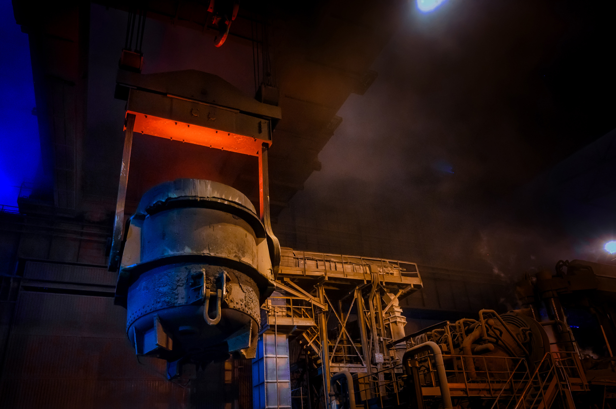
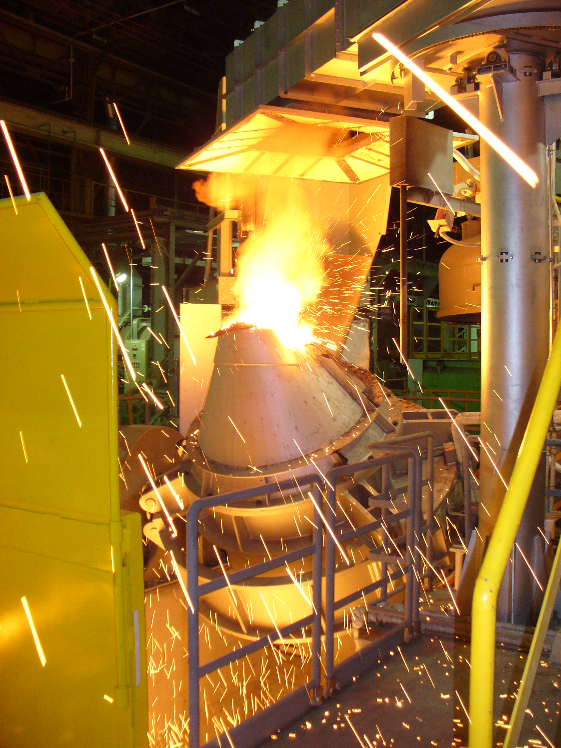
Every electric arc furnace relies on a step-down transformer to convert high-voltage grid power into low-voltage, high-current energy suitable for melting scrap or DRI.
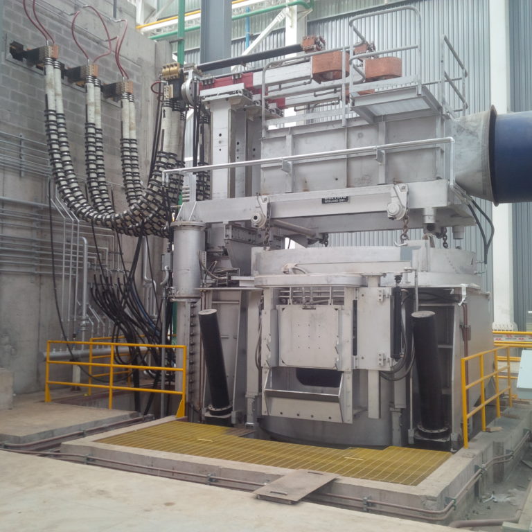
Whiting Equipment Canada (WEC), in partnership with Norsk Trafo Service AS (NTS), supplies both shell and core type transformers designed for steelmaking, mineral fusion, and non-ferrous melting applications. Each unit is custom-engineered in Norway using premium windings and insulation systems.
The shell-type design is preferred for EAF service because of its compact footprint, lighter weight, and—most importantly—its lower impedance, which improves power transfer efficiency and shortens melt time. A single installation example cited by Whiting reused a 75,000 kVA transformer during an Eccentric Bottom Tap (EBT) furnace upgrade, illustrating how correct sizing and robust design allow decades of reuse.
Sizing Criteria and Constraints
Transformer sizing begins by matching the furnace power demand to the melting rate while ensuring electrical stability. The core principle: minimize impedance to maximize power delivery to the arc.
Key criteria include:
- Impedance: Shell-type transformers have roughly ½ to ⅓ the reactance of comparable core designs, which allows higher secondary current at the same voltage.
- Flux Density: Lower magnetic flux density reduces saturation and improves response during bore-down and cave-in phases.
- Voltage Regulation Range: A broad tap range supports fine adjustment across melting, refining, and superheating stages.
These design parameters determine the transformer’s ability to deliver stable current without excessive flicker, harmonics, or heat buildup.
Secondary Voltages and Tap Selection
The transformer’s secondary voltage governs arc intensity and penetration. During the melt phase, higher voltage promotes scrap penetration; later, lower voltage stabilizes the refining arc.
Modern shell-type EAF transformers provide:
- Large regulating range with many tap steps.
- Custom voltage gaps tuned to the furnace’s metallurgical profile.
- Integration with control systems such as Whiting’s Volta-SAF Regulator, which continuously adjusts electrode position and tap settings through proportional-error feedback.
Precise tap control ensures operators stay within the optimal power window, maintaining high productivity while protecting refractories and electrodes.
Cooling and Duty Cycles
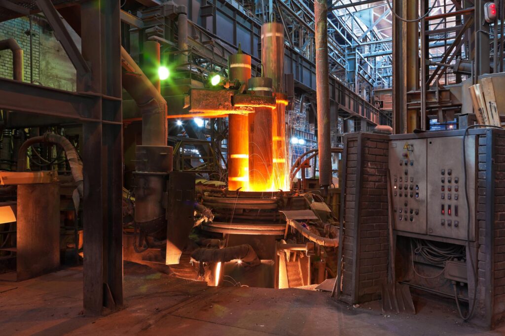
EAF transformers face severe cyclic loading. Rapid swings between full-power melt and idle conditions cause thermal stress that can shorten insulation life if cooling is inadequate.
Whiting/NTS shell-type designs manage this through:
- Direct, forced-oil cooling: Windings are cooled evenly through oil channels—no piping—reducing hot-spot temperatures.
- Solid-plate copper windings located directly in the oil stream, cutting the hot-spot gradient by up to 80 %.
- Lower total losses (ohmic + magnetic), improving energy efficiency and reducing the risk of overheating alarms during high-duty operation.
For monitoring, the Volta Furnace Master control system provides dedicated Transformer Status and Cooling Status screens that track temperature, flow, and electrical parameters in real time. If the cooling flow drops or the temperature rises beyond thresholds, interlocks automatically restrict the load to prevent insulation damage.
Calculating Power Demand — From MVA to kWh/t
Transformer MVA rating defines the furnace’s maximum power throughput. To connect this to operational efficiency, energy consumption per ton (kWh/t) can be estimated using logged production data.
Required variables:
- Transformer apparent power (MVA = kV × kA × √3 / 1000)
- Tap-to-tap time (minutes)
- Heat weight (t/heat)
- Logged energy use (from Volta Furnace Master modules)
Example:
A 75 MVA transformer operating at 85 % load for a 60-minute heat that produces 120 t of steel would deliver roughly 31,000 kWh per heat, or about 260 kWh/t, aligning with typical EBT furnace benchmarks.
Tracking this ratio over time reveals trends in refractory wear, power loss, and efficiency drift—vital metrics for scheduling relines and maintenance.
Losses, Overheating & Alarms
Thermal performance is the hidden determinant of transformer longevity. Losses arise from:
- Winding resistance (I²R) — increases with current and temperature.
- Core hysteresis and eddy currents.
- Stray flux and connections at bus bars and bushings.
Each adds to the oil temperature and dielectric stress. Modern monitoring software triggers alarms before oil temperature, winding temperature, or cooling flow exceed safe thresholds. Operators can view these parameters on the Furnace Master dashboard to pre-empt failures.
Spec Checklist for Procurement or RFQs
When specifying a new EAF transformer—or auditing an existing one—consider including these questions in your RFQ or design review:
- Type and Configuration: Shell or core? Is the design optimized for low reactance and high secondary current?
- MVA Rating and Tap Range: What secondary voltage steps are provided, and can gaps be customized?
- Cooling Method: Natural oil-air, forced-oil, or water-oil heat exchangers? What redundancy exists for fans or pumps?
- Duty Cycle Rating: Is the unit rated for continuous or cyclic EAF duty (typically 80–90 % load factor)?
- Impedance (% Z): Lower values improve power transfer but may raise short-circuit currents—does plant protection allow for it?
- Monitoring & Interlocks: Are thermal sensors, oil-flow alarms, and interlocks integrated with the main PLC/SCADA system?
- Maintenance Access: Can tap changers, bushings, and cooling components be serviced without draining oil?
- Space and Weight Constraints: Will the transformer fit existing vault dimensions and crane limits?
A well-written specification reduces procurement risk and ensures that the delivered unit meets both electrical and mechanical performance expectations.
The Bottom Line
Whiting experts are ready to be your EAF transformer sizing guide. We will show you how to balance electrical power, metallurgical demand, and plant constraints. Oversizing increases cost and reactive-power penalties; undersizing limits melt rate and strains electrodes.
Shell-type, low-impedance transformers—combined with precise digital regulation and real-time monitoring—remain the most efficient path to faster, safer, and more predictable melts.
For melt shops planning a retrofit or expansion, Whiting’s engineering team and its NTS partners can model MVA requirements, verify compatibility with existing bus and vault systems, and deliver a transformer specification that aligns power supply, productivity, and lifecycle cost from the first tap to the last. Contact us to discuss your requirements.